例子

目录
本页上的示例可以帮助你学习如何使用 CadQuery 构建对象。
这些示例的组织方式从简单到复杂,因此按顺序进行是吸收它们的最佳方式。
每个示例都列出了示例中使用的 API 元素,以便于参考。示例中引入的项目标有!
我们强烈建议您安装 CQ-editor,这样您就可以与这些示例进行交互式操作。更多信息,请参阅 Installing CadQuery。
如果您要这样做,请确保采取以下步骤,使它们发挥作用:
将 cadquery 导入为
cqshow_object(result)在末尾添加该行。下面的示例是自动生成的,但它们使用的语法与网站上的模型所需的语法不同。
1、简易矩形板
最简单的例子,一个矩形盒子:
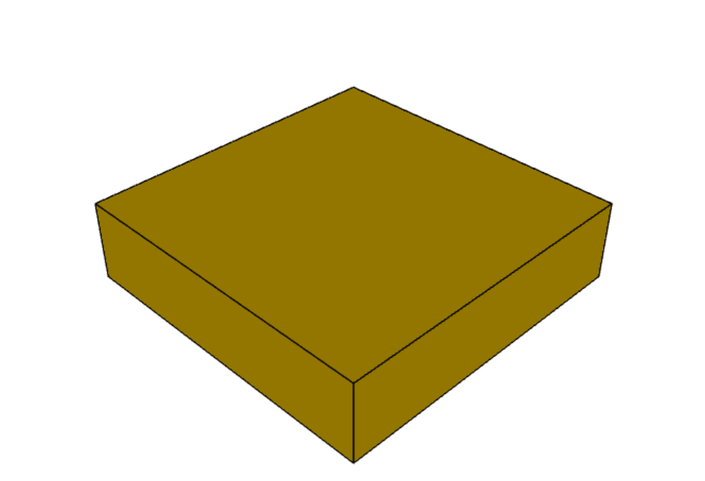
result = cq.Workplane("front").box(2.0, 2.0, 0.5)Api 参考:Workplane()Workplane.box()
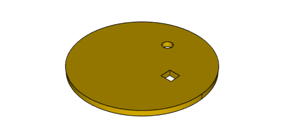
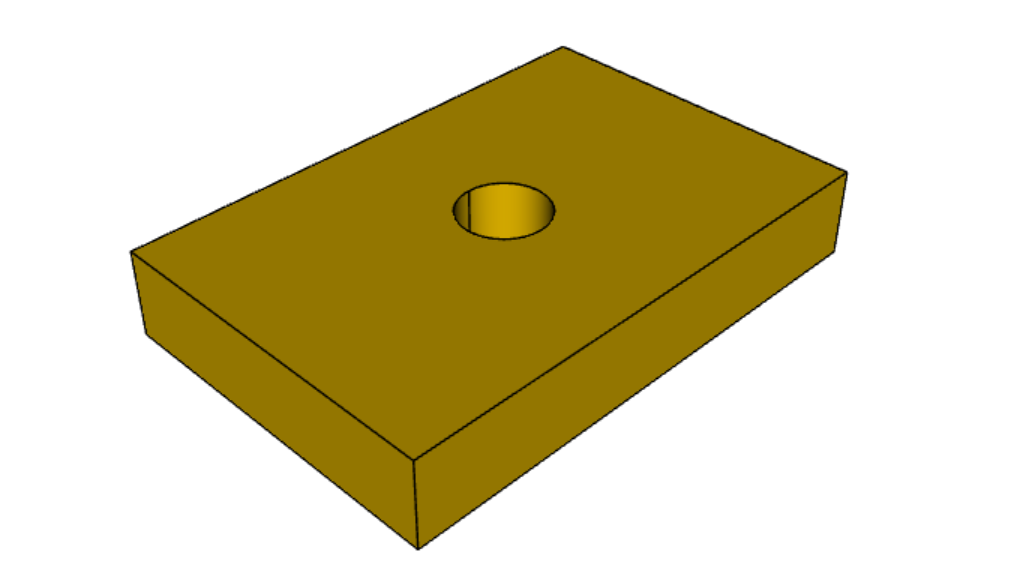
2、带孔板
一个矩形盒子,但添加了一个孔。>Z 选择盒子的最顶面。 孔位于中心,因为工作平面的默认原点是最后一个工作平面的投影原点,最后一个工作平面的原点为 (0,0,0),投影位于面的中心。 默认孔深贯穿整个零件。

# The dimensions of the box. These can be modified rather than changing the
# object's code directly.
length = 80.0
height = 60.0
thickness = 10.0
center_hole_dia = 22.0

# Create a box based on the dimensions above and add a 22mm center hole
result = (cq.Workplane("XY").box(length, height, thickness).faces(">Z").workplane().hole(center_hole_dia))
Api 参考:Workplane.hole() Workplane.box()
3、挤压棱柱体
使用挤压构建棱柱体。 绘制操作后,将前一个对象的中心放入栈中,作为下一次操作的参考。 所以在这个例子中, rect() 会在先前绘制的圆上居中绘制。
默认情况下,矩形和圆形以前一个工作点为中心。
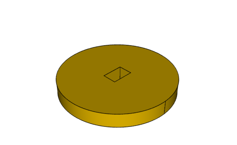
result = cq.Workplane("front").circle(2.0).rect(0.5, 0.75).extrude(0.5)Api 参考: Workplane.circle() Workplane.rect() Workplane.extrude() Workplane()
4、使用线和弧构建轮廓
有时你需要使用直线和弧线构建复杂的轮廓。 此示例通过 2D 操作构建棱柱实体。
2D 操作维护当前点,该点最初位于原点。 使用 close() 完成闭合曲线。
result = (
    cq.Workplane("front")
    .lineTo(2.0, 0)
    .lineTo(2.0, 1.0)
    .threePointArc((1.0, 1.5), (0.0, 1.0))
    .close()
    .extrude(0.25)
)
Api 参考:Workplane.threePointArc() Workplane.lineTo() Workplane.extrude()Workplane()
5、移动当前工作点
在这个例子中,需要一个封闭的轮廓,并且有一些内部特征。
此示例还演示了使用多行代码而不是较长的链式命令,当然在这种情况下也可以在一长行中完成。
可以在任何一点建立一个新的工作平面中心。
result = cq.Workplane("front").circle(
    5.0
)  # current point is the center of the circle, at (0, 0)
result = result.center(1.5, 0.0).rect(0.5, 0.5)  # new work center is (1.5, 0.0)

result = result.center(-1.5, 1.5).circle(0.25)  # new work center is (0.0, 1.5).
# The new center is specified relative to the previous center, not global coordinates!

result = result.extrude(0.25)注意:center 参数是相对位置
第一个 center(1.5, 0.0) 是相对于(0, 0),即默认的中心点
第二个 center(-1.5, 1.5) 是相对于 (1.5, 0.0),因为第一个center改变了中心点位置
Api 参考: Workplane.center() Workplane()Workplane.circle() Workplane.rect()Workplane.extrude()
6、使用点列表
有时你需要在不同位置创建多个特征,使用 Workplane.center() 太麻烦了。
可以使用点列表一次构造多个对象。 大多数构造方法,如 Workplane.circle() 和 Workplane.rect(),将会对堆栈中的多个点进行操作。
r = cq.Workplane("front").circle(2.0)  # make base
r = r.pushPoints(
    [(1.5, 0), (0, 1.5), (-1.5, 0), (0, -1.5)]
)  # now four points are on the stack
r = r.circle(0.25)  # circle will operate on all four points
result = r.extrude(0.125)  # make prism
Api 参考:Workplane.pushPoints() Workplane() Workplane.circle() Workplane.extrude()
7、多边形
如果愿意,你可以为栈上的每个点创建多边形。 适用于固件无法修正小孔尺寸的 3d 打印机。
result = (
    cq.Workplane("front")
    .box(3.0, 4.0, 0.25)
    .pushPoints([(0, 0.75), (0, -0.75)])
    .polygon(6, 1.0)
    .cutThruAll()
)
Api 参考: Workplane.polygon() Workplane.pushPoints() Workplane.box()
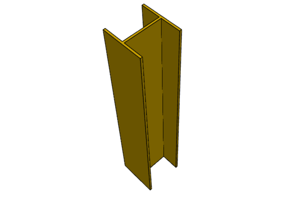
8、折线
Workplane.polyline() 可以通过由线连接的一系列点创建形状。
此示例使用折线创建工字梁形状的一半,然后对其进行镜像以创建最终轮廓。

(L, H, W, t) = (100.0, 20.0, 20.0, 1.0)
pts = [
    (0, H/2.0),
    (W/2.0, H/2.0),
    (W/2.0, (H/2.0 - t)),
    (t/2.0, (H/2.0 - t)),
    (t/2.0, (t - H/2.0)),
    (W/2.0, (t - H/2.0)),
    (W/2.0, H/-2.0),
    (0, H/-2.0)
]
result = cq.Workplane("front").polyline(pts).mirrorY().extrude(L)
Api 参考: Workplane.polyline() Workplane() Workplane.mirrorY()Workplane.extrude()
9、用样条曲线定义边
该示例通过点集合使用样条曲线定义一个边。 在需要复杂轮廓的边缘时非常有用。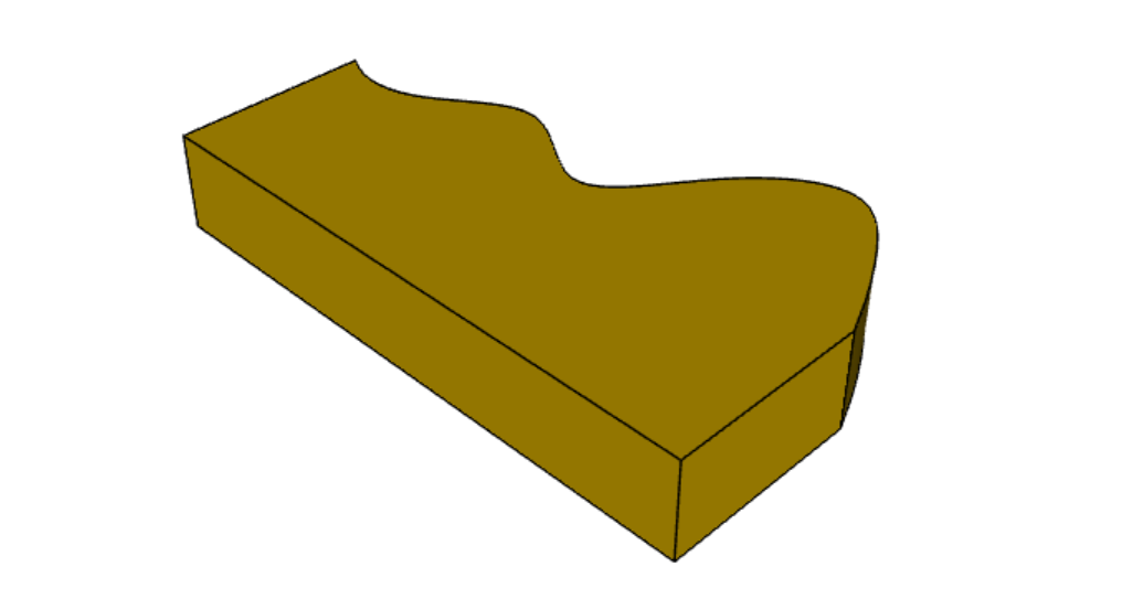
s = cq.Workplane("XY")
sPnts = [
    (2.75, 1.5),
    (2.5, 1.75),
    (2.0, 1.5),
    (1.5, 1.0),
    (1.0, 1.25),
    (0.5, 1.0),
    (0, 1.0),
]
r = (
    s.lineTo(3.0, 0)
    .lineTo(3.0, 1.0)
    .spline(sPnts, includeCurrent=True)
    .close()
)
result = r.extrude(0.5)
Api 参考:Workplane.spline() Workplane()Workplane.close() Workplane.lineTo()Workplane.extrude()
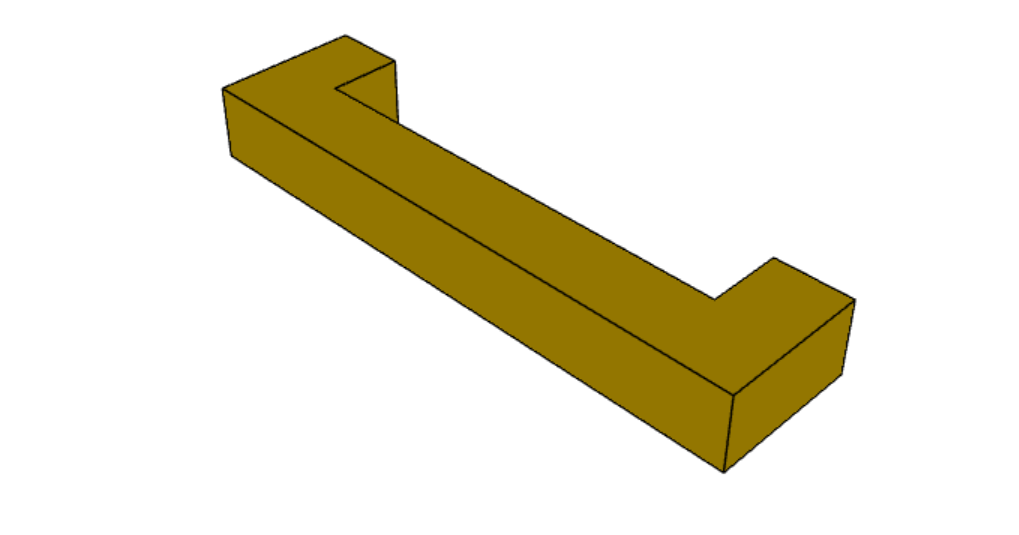
10、镜像几何形状
当你的几何形状对称时,可以镜像 2D 几何体。 在这个例子中,我们还引入了水平线和垂直线,这使得编码稍微容易一些。
r = cq.Workplane("front").hLine(1.0)  # 1.0 is the distance, not coordinate
r = (
    r.vLine(0.5)
    .hLine(-0.25)
    .vLine(-0.25)
    .hLineTo(0.0)
)  # hLineTo allows using xCoordinate not distance
result = r.mirrorY().extrude(0.25)  # mirror the geometry and extrude
Api 参考: Workplane.hLine() Workplane.vLine() Workplane.hLineTo() Workplane.mirrorY() Workplane.mirrorX() Workplane()Workplane.extrude()
11、镜像三维对象
result0 = (
    cq.Workplane("XY")
    .moveTo(10, 0)
    .lineTo(5, 0)
    .threePointArc((3.9393, 0.4393), (3.5, 1.5))
    .threePointArc((3.0607, 2.5607), (2, 3))
    .lineTo(1.5, 3)
    .threePointArc((0.4393, 3.4393), (0, 4.5))
    .lineTo(0, 13.5)
    .threePointArc((0.4393, 14.5607), (1.5, 15))
    .lineTo(28, 15)
    .lineTo(28, 13.5)
    .lineTo(24, 13.5)
    .lineTo(24, 11.5)
    .lineTo(27, 11.5)
    .lineTo(27, 10)
    .lineTo(22, 10)
    .lineTo(22, 13.2)
    .lineTo(14.5, 13.2)
    .lineTo(14.5, 10)
    .lineTo(12.5, 10)
    .lineTo(12.5, 13.2)
    .lineTo(5.5, 13.2)
    .lineTo(5.5, 2)
    .threePointArc((5.793, 1.293), (6.5, 1))
    .lineTo(10, 1)
    .close()
)
result = result0.extrude(100)

result = result.rotate((0, 0, 0), (1, 0, 0), 90)

result = result.translate(result.val().BoundingBox().center.multiply(-1))

mirXY_neg = result.mirror(mirrorPlane="XY", basePointVector=(0, 0, -30))
mirXY_pos = result.mirror(mirrorPlane="XY", basePointVector=(0, 0, 30))
mirZY_neg = result.mirror(mirrorPlane="ZY", basePointVector=(-30, 0, 0))
mirZY_pos = result.mirror(mirrorPlane="ZY", basePointVector=(30, 0, 0))

result = result.union(mirXY_neg).union(mirXY_pos).union(mirZY_neg).union(mirZY_pos)
Api References:Workplane.moveTo() Workplane.lineTo() Workplane.threePointArc()Workplane.extrude() Workplane.mirror()Workplane.union()Workplane.rotate()
12、参考面镜像
此示例显示如何围绕选定的面进行镜像。 示例还展示了如何将生成的镜像对象立即与引用的几何体合并。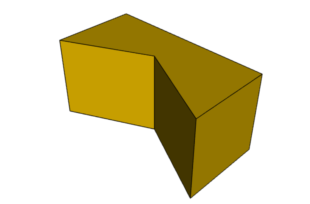
result = (cq.Workplane("XY")
          .line(0, 1)
          .line(1, 0)
          .line(0, -.5)
          .close()
          .extrude(1))

result = result.mirror(result.faces(">X"), union=True)
Api References:Workplane.line()Workplane.close() Workplane.extrude() Workplane.faces()Workplane.mirror()Workplane.union()
13、在面上创建工作平面
此示例说明如何在先前创建的特征的面上定位新工作平面。
以这种方式使用工作平面是 CadQuery 的一个关键特性。 与典型的 3d 脚本语言不同,使用工作平面使你无需跟踪变量中各种特征的位置,并允许模型通过删除冗余尺寸进行自我调整。
Workplane.faces() 方法允许你选择生成的实体的面。 它接受一个选择器字符串或对象,允许你以单个面为目标,并面向该面生成一个工作平面。
请记住,默认情况下,新工作平面的原点,是通过从所选面形成一个平面,并将先前的原点投影到该平面上来计算的。 可以通过 Workplane.workplane() 的 centerOption 参数更改此行为。
result = cq.Workplane("front").box(2, 3, 0.5)  # make a basic prism
result = (
    result.faces(">Z")
    .workplane()
    .hole(0.5)
)  # find the top-most face and make a hole
Api References:Workplane.faces() StringSyntaxSelector() Selectors Reference Workplane.workplane() Workplane.box()Workplane()
14、在顶点上定位工作平面
通常, Workplane.workplane()方法需要选择一个面。 但是,如果在选中一个面后且立即选择顶点,将 centerOption 参数设置为 CenterOfMass 时,Workplane.workplane()会将工作平面定位在面上,原点位于顶点而不是面的中心。
本示例还介绍了 Workplane.cutThruAll(),它对整个零件进行切割,无论零件有多深。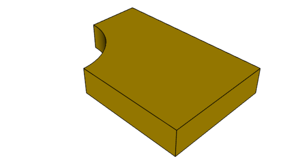
result = cq.Workplane("front").box(3, 2, 0.5)  # make a basic prism
result = (
    result.faces(">Z")
    .vertices("<XY")
    .workplane(centerOption="CenterOfMass")
)  # select the lower left vertex and make a workplane
result = result.circle(1.0).cutThruAll()  # cut the corner out
Api References:Workplane.cutThruAll() Selectors Reference Workplane.vertices() Workplane.box()Workplane()StringSyntaxSelector()
15、偏移工作平面
工作平面不必完全位于面上。制作工作平面时,可以将其定义在现有面的偏移位置。
本示例使用偏移工作平面制作复合对象,完全有效!
result = cq.Workplane("front").box(3, 2, 0.5)  # make a basic prism
result = result.faces("<X").workplane(
    offset=0.75
)  # workplane is offset from the object surface
result = result.circle(1.0).extrude(0.5)  # disc
Api References:Workplane.extrude() Selectors Reference Workplane.box()Workplane()
16、复制工作平面
现有的 CQ 对象可以从另一个 CQ 对象复制工作平面
result = (
    cq.Workplane("front")
    .circle(1)
    .extrude(10)  # 做圆柱
    # 我们要制作与第一个圆柱垂直的第二个圆柱
    # 但我们没有工作面作为基础
    .copyWorkplane(
        # 创建一个包含所需工作平面的临时对象
        cq.Workplane("right", origin=(-5, 0, 0))
    )
    .circle(1)
    .extrude(10)
)
API References:Workplane.copyWorkplane() Workplane.circle() Workplane.extrude()Workplane()
17、旋转工作平面
可以创建一个相对于另一个工作平面旋转指定角度的工作平面。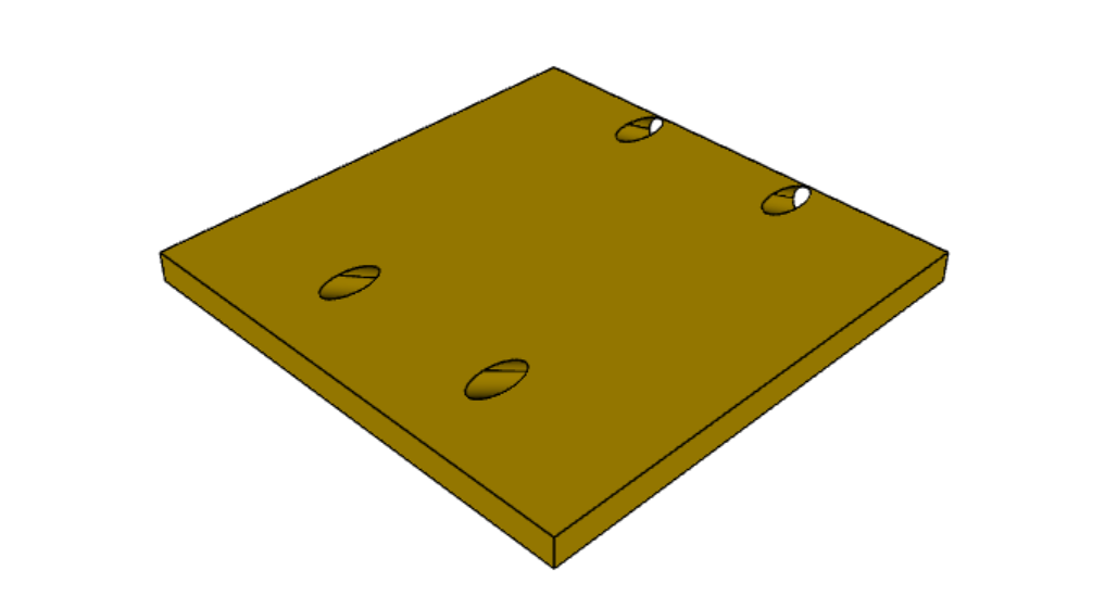
result = (
    cq.Workplane("front")
    .box(4.0, 4.0, 0.25)
    .faces(">Z")
    .workplane()
    .transformed(offset=cq.Vector(0, -1.5, 1.0), rotate=cq.Vector(60, 0, 0))
    .rect(1.5, 1.5, forConstruction=True)
    .vertices()
    .hole(0.25)
)
使用 transformed 前后的工作平面变化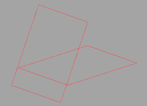
Api References:Workplane.transformed() Workplane.box() Workplane.rect()Workplane.faces()
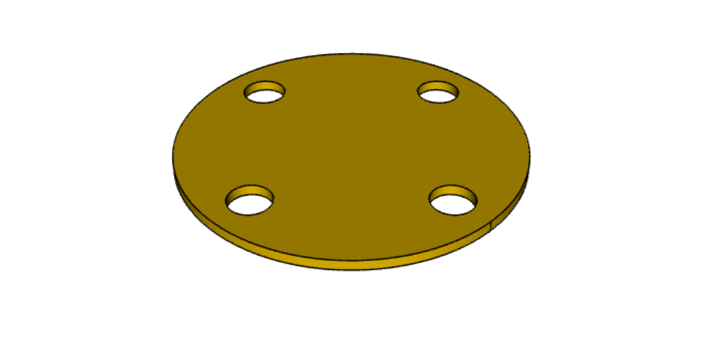
18、使用构造几何
您可以绘制形状,将其顶点作为点来定位其他特征,但这个形状本身并不用于构造几何。
这种用于定位其他特征,而不创建几何的特征,称为构造几何Construction Geometry。
在下面的示例中,绘制了一个矩形,其顶点用于定位一组孔。

result = (
    cq.Workplane("front")
    .box(2, 2, 0.5)
    .faces(">Z")
    .workplane()
    .rect(1.5, 1.5, forConstruction=True)
    .vertices()
    .hole(0.125)
)
Api References: Workplane.rect() (forConstruction=True) Selectors Reference Workplane.workplane() Workplane.box()Workplane.hole()Workplane()
19、抽壳创建薄壁特征
抽壳是将实体对象转换为厚度均匀的壳。
使用形状的Workplane.shell()方法 ,传入一个负的厚度参数,就可以给对象抽壳并“挖空”内部。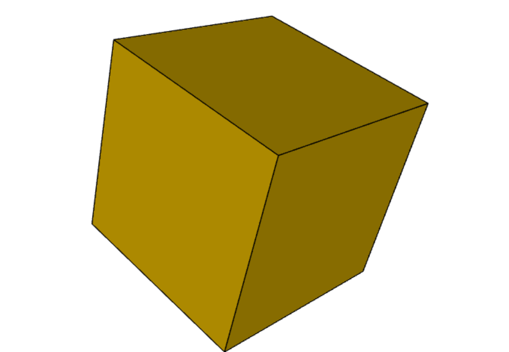
result = cq.Workplane("front").box(2, 2, 2).shell(-0.1)正的厚度参数用圆角外边缘包裹对象,原始对象将是“挖空”部分。

result = cq.Workplane("front").box(2, 2, 2).shell(0.1)使用面选择器,选择要从生成的空心形状中删除的面。

result = cq.Workplane("front").box(2, 2, 2).faces("+Z").shell(0.1)可以使用更复杂的选择器删除多个面。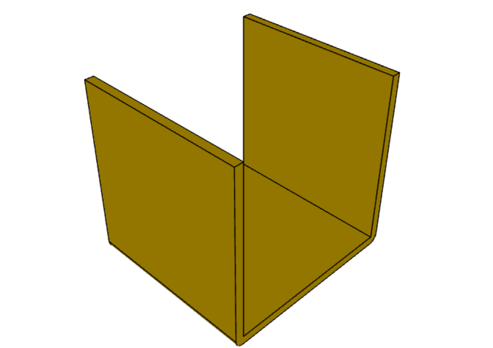
result = (
     cq.Workplane("front")
     .box(2, 2, 2)
     .faces("+Z or -X or +X")
     .shell(0.1)
)
Api References:Workplane.shell() Selectors ReferenceWorkplane.box() Workplane.faces()Workplane()
20、放样
放样是一组线扫掠得到实体。 此示例在矩形和圆形截面之间创建放样截面。

result = (
    cq.Workplane("front")
    .box(4.0, 4.0, 0.25)
    .faces(">Z")
    .circle(1.5)
    .workplane(offset=3.0)
    .rect(0.75, 0.5)
    .loft(combine=True)
)
Api References: Workplane.loft() Workplane.box()Workplane.faces()
21、挤压至指定面
有时你会想要挤出一条线直到给定的面,这个面可能不是平面,或者你可能不容易知道必须挤出的距离。 在这种情况下,可以使用 next、 last 或 Face对象 作为 extrude() 终止条件的参数 。

result = (
    cq.Workplane(origin=(20, 0, 0))
    .circle(2)
    .revolve(180, (-20, 0, 0), (-20, -1, 0))
    .center(-20, 0)
    .workplane()
    .rect(20, 4)
    .extrude("next")
)
cutBlind() 也有相同的功能,也可以一次处理多个 Wire 线对象(extrude() 也有同样的功能)。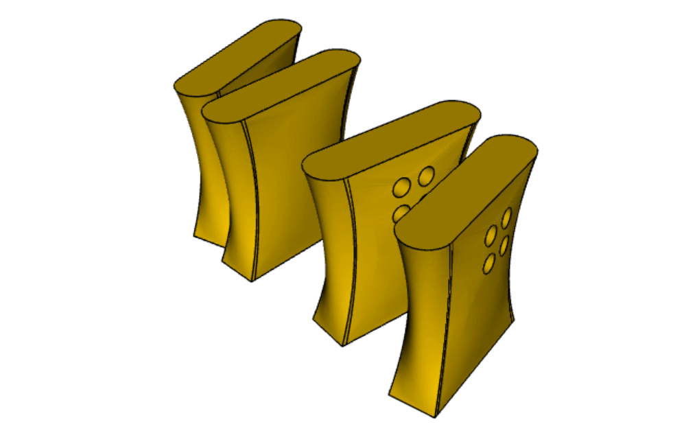
skyscrapers_locations = [(-16, 1), (-8, 0), (7, 0.2), (17, -1.2)]
angles = iter([15, 0, -8, 10])
skyscrapers = (
    cq.Workplane()
    .pushPoints(skyscrapers_locations)
    .eachpoint(
        lambda loc: (
            cq.Workplane()
            .rect(5, 16)
            .workplane(offset=10)
            .ellipse(3, 8)
            .workplane(offset=10)
            .slot2D(20, 5, 90)
            .loft()
            .rotateAboutCenter((0, 0, 1), next(angles))
            .val()
            .located(loc)
        )
    )
)

result = (
    skyscrapers.transformed((0, -90, 0))
    .moveTo(15, 0)
    .rect(3, 3, forConstruction=True)
    .vertices()
    .circle(1)
    .cutBlind("last")
)
这是一个典型的情况,挤压和切割到给定的面非常方便。 它允许我们挤压或切割直到曲面,而不会出现重叠问题。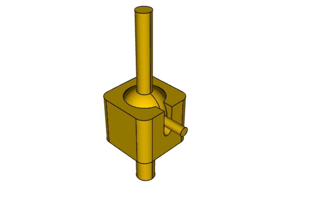
sphere = cq.Workplane().sphere(5)
base = cq.Workplane(origin=(0, 0, -2)).box(12, 12, 10).cut(sphere).edges("|Z").fillet(2)
sphere_face = base.faces(">>X[2] and (not |Z) and (not |Y)").val()
base = base.faces("<Z").workplane().circle(2).extrude(10)

shaft = cq.Workplane().sphere(4.5).circle(1.5).extrude(20)

spherical_joint = (
    base.union(shaft)
    .faces(">X")
    .workplane(centerOption="CenterOfMass")
    .move(0, 4)
    .slot2D(10, 2, 90)
    .cutBlind(sphere_face)
    .workplane(offset=10)
    .move(0, 2)
    .circle(0.9)
    .extrude("next")
)

result = spherical_joint
show_object(result)如果你想要挤出的线不能完全投影到目标表面上,结果将是不可预测的。此外,负责查找候选面的算法通过计算与从线中心沿挤出方向创建的线相交的所有面来进行搜索。因此,请确保您的线可以投射到目标面上,以避免出现意外行为。
Api References:Workplane.cutBlind() Workplane.rect()Workplane.ellipse() Workplane.workplane() Workplane.slot2D() Workplane.loft()Workplane.rotateAboutCenter() Workplane.transformed() Workplane.moveTo() Workplane.circle() |
22、制作沉头孔和埋头孔
沉头孔和埋头孔非常常见,以至于 CadQuery 专门创建宏以便用一个简单的步骤来创建它们。
埋头孔:
形状: 埋头孔在顶部具有较大直径,然后过渡到较小直径的孔。
用途: 顶部较大的直径旨在容纳螺栓或螺钉的头部,而下面较小的直径是用来容纳螺纹部分的。这种设计使得紧固件的头部可以位于表面以下,提供平坦或齐平的外观。
沉头孔:
形状: 沉头孔呈锥形,表面处有较宽的开口,然后逐渐变为较小直径的孔。
用途: 较宽的开口设计用来容纳螺钉或螺栓的头部。锥形的形状使得头部可以与表面齐平或稍微低于表面,提供平滑和美观的外观。沉头孔通常在外观是关键考虑因素时使用。
总的来说,主要区别在于这些孔的形状和用途。埋头孔具有阶梯状的形状,适应紧固件的头部,而沉头孔具有锥形的形状,使得紧固件的头部可以与表面齐平或稍微低于表面,以获得更流畅的外观。选择取决于应用的具体要求和期望的美观效果。
与 Workplane.hole()类似,这些函数对点列表以及单个点进行操作。

result = (
    cq.Workplane(cq.Plane.XY())
    .box(4, 2, 0.5)
    .faces(">Z")
    .workplane().tag("p1")
    .rect(3.5, 1.5, forConstruction=True)
    .vertices()
    .cboreHole(0.125, 0.25, 0.125, depth=None) # 埋头孔
)
result = (
    result.workplaneFromTagged("p1")
    .rect(2.5, 1.5, forConstruction=True)
    .vertices()
    .cskHole(0.125, 0.25, 82, depth=None)  # 沉头孔
)
Api References: Workplane.cboreHole() Workplane.cskHole() Workplane.box()Workplane.rect()Workplane.workplane()Workplane.vertices() Workplane.faces() Workplane()
23、2D 中的偏移线
可以使用Workplane.offset2D()转换二维线。 它们可以向内或向外偏移,并采用不同的技术来延伸边角。
original = cq.Workplane().polygon(5, 10).extrude(0.1).translate((0, 0, 2))
arc = cq.Workplane().polygon(5, 10).offset2D(1, "arc").extrude(0.1).translate((0, 0, 1))
intersection = cq.Workplane().polygon(5, 10).offset2D(1, "intersection").extrude(0.1)
result = original.add(arc).add(intersection)
使用 forConstruction 参数,你可以执行从对象轮廓偏移一系列螺栓孔的常见任务。 这是上面的埋头孔示例,但螺栓孔是从边缘偏离的。
result = (
    cq.Workplane()
    .box(4, 2, 0.5)
    .faces(">Z")
    .edges()
    .toPending()
    .offset2D(-0.25, forConstruction=True)
    .vertices()
    .cboreHole(0.125, 0.25, 0.125, depth=None)
)
请注意, Workplane.edges() 用于选择对象。 它不会将选定的边缘添加到建模上下文中的待定边缘中,因为这会导致你的下一次挤压包括你选择的所有内容,出了绘制的线条外。 如果希望在 Workplane.offset2D() 中使用这些边,可以调用 Workplane.toPending() 以明确地将它们放入待定边缘列表中。
Api References: Workplane.offset2D() Workplane.cboreHole() Workplane.cskHole() Workplane.box()Workplane.polygon()Workplane.workplane() Workplane.vertices() Workplane.edges() Workplane.faces() Workplane()
24、圆角
圆角是通过选择实体的边缘并使用 fillet() 功能来完成的。
在这里,我们对一个简单平板的所有边缘进行圆角处理。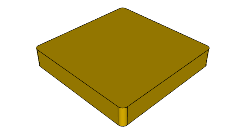
result = cq.Workplane("XY").box(3, 3, 0.5).edges("|Z").fillet(0.125)Api References:Workplane.fillet() Workplane.box() Workplane.edges() Workplane()
25、标记对象
Workplane.tag() 方法可用于用字符串标记链中的特定对象,以便稍后在链中引用它。
Workplane.workplaneFromTagged() 方法将应用 Workplane.copyWorkplane() 复制标记对象后返回。 例如,当从同一个表面挤出两个不同的实体时,在第一个实体被挤出后,很难用 CadQuery 的其他选择器重新选择原始表面。
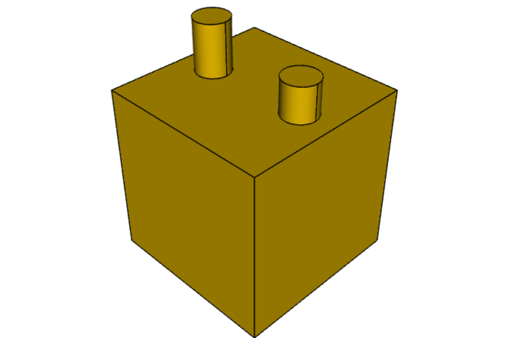
result = (
    cq.Workplane("XY")
    # create and tag the base workplane
    .box(10, 10, 10)
    .faces(">Z")
    .workplane()
    .tag("baseplane")
    # extrude a cylinder
    .center(-3, 0)
    .circle(1)
    .extrude(3)
    # to reselect the base workplane, simply
    .workplaneFromTagged("baseplane")
    # extrude a second cylinder
    .center(3, 0)
    .circle(1)
    .extrude(2)
)标签也可以与大多数选择器一起使用,包括Workplane.vertices(), Workplane.faces(), Workplane.edges(), Workplane.wires(), Workplane.shells(), Workplane.solids() and Workplane.compounds()。
result = (
    cq.Workplane("XY")
    # create a triangular prism and tag it
    .polygon(3, 5)
    .extrude(4)
    .tag("prism")
    # create a sphere that obscures the prism
    .sphere(10)
    # create features based on the prism's faces
    .faces("<X", tag="prism")
    .workplane()
    .circle(1)
    .cutThruAll()
    .faces(">X", tag="prism")
    .faces(">Y")
    .workplane()
    .circle(1)
    .cutThruAll()
)
Api References: Workplane.tag() Workplane.getTagged()Workplane.workplaneFromTagged() Workplane.extrude() Workplane.cutThruAll() Workplane.circle() Workplane.faces()Workplane()
26、参数化轴承座
结合一些基本功能,只需几行代码,就可以制作出非常好的参数化轴承座。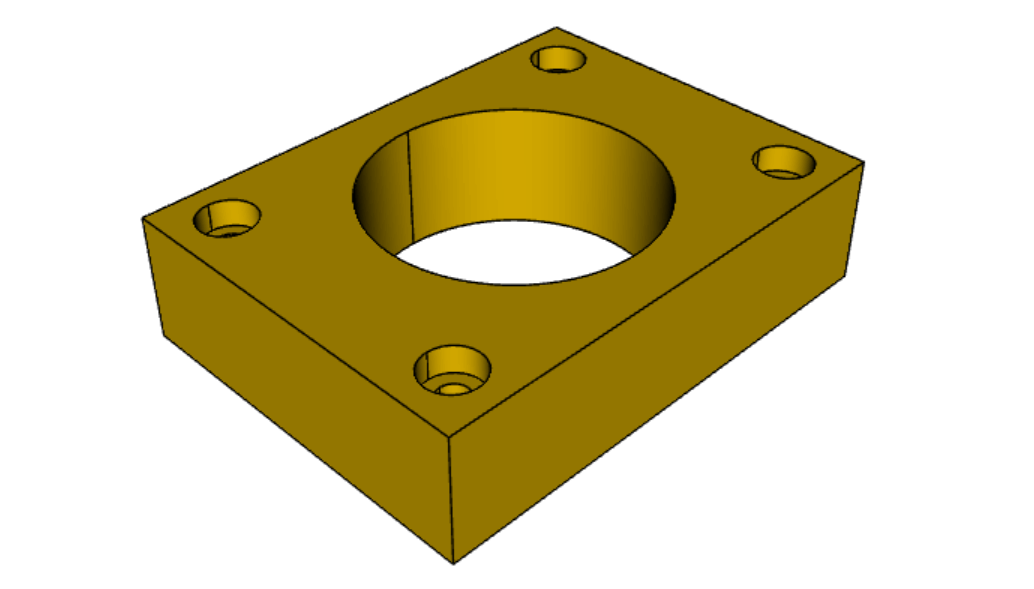
(length, height, bearing_diam, thickness, padding) = (30.0, 40.0, 22.0, 10.0, 8.0)

result = (
    cq.Workplane("XY")
    .box(length, height, thickness)
    .faces(">Z")
    .workplane()
    .hole(bearing_diam)
    .faces(">Z")
    .workplane()
    .rect(length - padding, height - padding, forConstruction=True)
    .vertices()
    .cboreHole(2.4, 4.4, 2.1)
)
27、分割对象
可以使用工作平面分割对象,并保留其中一个或两个部分。
c = cq.Workplane("XY").box(1, 1, 1).faces(">Z").workplane().circle(0.25).cutThruAll()

# now cut it in half sideways
result = c.faces(">Y").workplane(-0.5).split(keepTop=True).clean()
show_object(result)
Api References: Workplane.split() Workplane.box()Workplane.circle() Workplane.cutThruAll() Workplane.workplane() Workplane()
28、经典 OCC 瓶
CadQuery 基于 OpenCascade.org (OCC) 建模内核。 熟悉 OCC 的人都知道著名的瓶子示例。The bottle example in the OCCT online documentation.
对应 pythonOCC 版本示例在 这里。
当然,此示例与 OCC 版本之间的一个区别是长度。 这个示例是 13 行的较长示例之一,但与 pythonOCC 版本相比非常短,pythonOCC长10 倍!
(L, w, t) = (20.0, 6.0, 3.0)
s = cq.Workplane("XY")

# Draw half the profile of the bottle and extrude it
p = (
    s.center(-L / 2.0, 0)
    .vLine(w / 2.0)
    .threePointArc((L / 2.0, w / 2.0 + t), (L, w / 2.0))
    .vLine(-w / 2.0)
    .mirrorX()
    .extrude(30.0, True)
)

# Make the neck
p = p.faces(">Z").workplane(centerOption="CenterOfMass").circle(3.0).extrude(2.0, True)

# Make a shell
result = p.faces(">Z").shell(0.3)
show_object(result)
Api References: Workplane.extrude() Workplane.mirrorX() Workplane.threePointArc() Workplane.workplane() Workplane.vertices() Workplane.vLine() Workplane.faces() Workplane()
29、参数化外壳
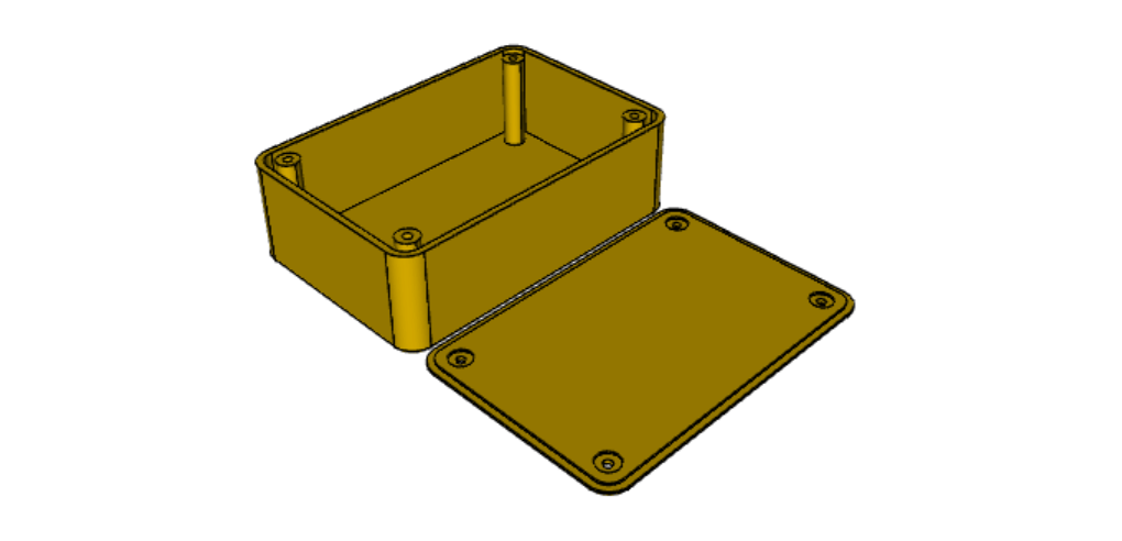
# parameter definitions
p_outerWidth = 100.0  # Outer width of box enclosure
p_outerLength = 150.0  # Outer length of box enclosure
p_outerHeight = 50.0  # Outer height of box enclosure

p_thickness = 3.0  # Thickness of the box walls
p_sideRadius = 10.0  # Radius for the curves around the sides of the box
p_topAndBottomRadius = (
    2.0  # Radius for the curves on the top and bottom edges of the box
)

p_screwpostInset = 12.0  # How far in from the edges the screw posts should be place.
p_screwpostID = 4.0  # Inner Diameter of the screw post holes, should be roughly screw diameter not including threads
p_screwpostOD = 10.0  # Outer Diameter of the screw posts.\nDetermines overall thickness of the posts

p_boreDiameter = 8.0  # Diameter of the counterbore hole, if any
p_boreDepth = 1.0  # Depth of the counterbore hole, if
p_countersinkDiameter = 0.0  # Outer diameter of countersink. Should roughly match the outer diameter of the screw head
p_countersinkAngle = 90.0  # Countersink angle (complete angle between opposite sides, not from center to one side)
p_flipLid = True  # Whether to place the lid with the top facing down or not.
p_lipHeight = 1.0  # Height of lip on the underside of the lid.\nSits inside the box body for a snug fit.

# outer shell
oshell = (
    cq.Workplane("XY")
    .rect(p_outerWidth, p_outerLength)
    .extrude(p_outerHeight + p_lipHeight)
)

# weird geometry happens if we make the fillets in the wrong order
if p_sideRadius > p_topAndBottomRadius:
    oshell = oshell.edges("|Z").fillet(p_sideRadius)
    oshell = oshell.edges("#Z").fillet(p_topAndBottomRadius)
else:
    oshell = oshell.edges("#Z").fillet(p_topAndBottomRadius)
    oshell = oshell.edges("|Z").fillet(p_sideRadius)

# inner shell
ishell = (
    oshell.faces("<Z")
    .workplane(p_thickness, True)
    .rect((p_outerWidth - 2.0 * p_thickness), (p_outerLength - 2.0 * p_thickness))
    .extrude(
        (p_outerHeight - 2.0 * p_thickness), False
    )  # set combine false to produce just the new boss
)
ishell = ishell.edges("|Z").fillet(p_sideRadius - p_thickness)

# make the box outer box
box = oshell.cut(ishell)

# make the screw posts
POSTWIDTH = p_outerWidth - 2.0 * p_screwpostInset
POSTLENGTH = p_outerLength - 2.0 * p_screwpostInset

box = (
    box.faces(">Z")
    .workplane(-p_thickness)
    .rect(POSTWIDTH, POSTLENGTH, forConstruction=True)
    .vertices()
    .circle(p_screwpostOD / 2.0)
    .circle(p_screwpostID / 2.0)
    .extrude(-1.0 * (p_outerHeight + p_lipHeight - p_thickness), True)
)

# split lid into top and bottom parts
(lid, bottom) = (
    box.faces(">Z")
    .workplane(-p_thickness - p_lipHeight)
    .split(keepTop=True, keepBottom=True)
    .all()
)  # splits into two solids

# translate the lid, and subtract the bottom from it to produce the lid inset
lowerLid = lid.translate((0, 0, -p_lipHeight))
cutlip = lowerLid.cut(bottom).translate(
    (p_outerWidth + p_thickness, 0, p_thickness - p_outerHeight + p_lipHeight)
)

# compute centers for screw holes
topOfLidCenters = (
    cutlip.faces(">Z")
    .workplane(centerOption="CenterOfMass")
    .rect(POSTWIDTH, POSTLENGTH, forConstruction=True)
    .vertices()
)

# add holes of the desired type
if p_boreDiameter > 0 and p_boreDepth > 0:
    topOfLid = topOfLidCenters.cboreHole(
        p_screwpostID, p_boreDiameter, p_boreDepth, 2.0 * p_thickness
    )
elif p_countersinkDiameter > 0 and p_countersinkAngle > 0:
    topOfLid = topOfLidCenters.cskHole(
        p_screwpostID, p_countersinkDiameter, p_countersinkAngle, 2.0 * p_thickness
    )
else:
    topOfLid = topOfLidCenters.hole(p_screwpostID, 2.0 * p_thickness)

# flip lid upside down if desired
if p_flipLid:
    topOfLid = topOfLid.rotateAboutCenter((1, 0, 0), 180)

# return the combined result
result = topOfLid.union(bottom)
show_object(result)
Api References: Workplane.circle()Workplane.rect()Workplane.extrude() Workplane.box()Workplane.all()Workplane.faces() Workplane.vertices()Workplane.edges() Workplane.workplane()Workplane.fillet()Workplane.cut() Workplane.union()Workplane.rotateAboutCenter()Workplane.cboreHole()Workplane.cskHole()Workplane.hole()
30、乐高积木
此脚本将生成任何尺寸的常规矩形 Lego™ 积木。 唯一棘手的是关于砖块底部的逻辑。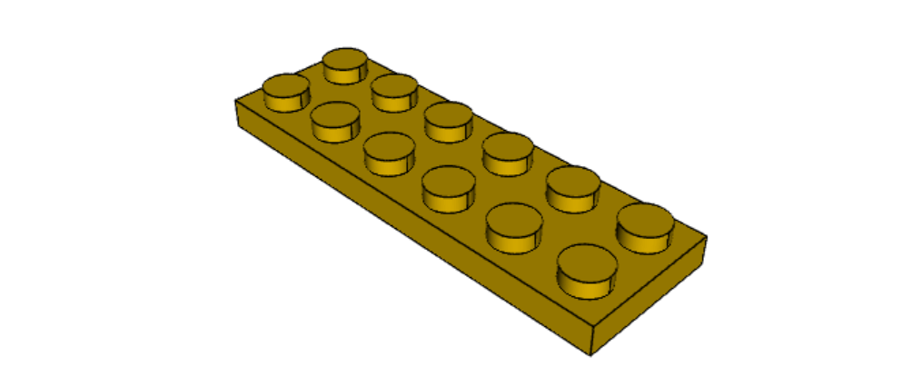
#####
# Inputs
######
lbumps = 6  # number of bumps long
wbumps = 2  # number of bumps wide
thin = True  # True for thin, False for thick

#
# Lego Brick Constants-- these make a Lego brick a Lego :)
#
pitch = 8.0
clearance = 0.1
bumpDiam = 4.8
bumpHeight = 1.8
if thin:
    height = 3.2
else:
    height = 9.6

t = (pitch - (2 * clearance) - bumpDiam) / 2.0
postDiam = pitch - t  # works out to 6.5
total_length = lbumps * pitch - 2.0 * clearance
total_width = wbumps * pitch - 2.0 * clearance

# make the base
s = cq.Workplane("XY").box(total_length, total_width, height)

# shell inwards not outwards
s = s.faces("<Z").shell(-1.0 * t)

# make the bumps on the top
s = (
    s.faces(">Z")
    .workplane()
    .rarray(pitch, pitch, lbumps, wbumps, True)
    .circle(bumpDiam / 2.0)
    .extrude(bumpHeight)
)

# add posts on the bottom. posts are different diameter depending on geometry
# solid studs for 1 bump, tubes for multiple, none for 1x1
tmp = s.faces("<Z").workplane(invert=True)

if lbumps > 1 and wbumps > 1:
    tmp = (
        tmp.rarray(pitch, pitch, lbumps - 1, wbumps - 1, center=True)
        .circle(postDiam / 2.0)
        .circle(bumpDiam / 2.0)
        .extrude(height - t)
    )
elif lbumps > 1:
    tmp = (
        tmp.rarray(pitch, pitch, lbumps - 1, 1, center=True)
        .circle(t)
        .extrude(height - t)
    )
elif wbumps > 1:
    tmp = (
        tmp.rarray(pitch, pitch, 1, wbumps - 1, center=True)
        .circle(t)
        .extrude(height - t)
    )
else:
    tmp = s
show_object(tmp)
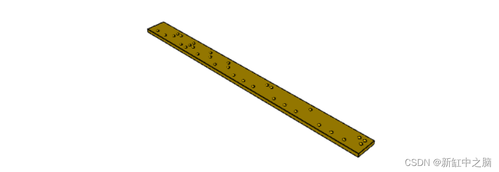
31、盲文示例
from collections import namedtuple
# text_lines is a list of text lines.
# Braille (converted with braille-converter:
# https://github.com/jpaugh/braille-converter.git).
text_lines = ['⠠ ⠋ ⠗ ⠑ ⠑ ⠠ ⠉ ⠠ ⠁ ⠠ ⠙']
# See http://www.tiresias.org/research/reports/braille_cell.htm for examples
# of braille cell geometry.
horizontal_interdot = 2.5
vertical_interdot = 2.5
horizontal_intercell = 6
vertical_interline = 10
dot_height = 0.5
dot_diameter = 1.3
base_thickness = 1.5
# End of configuration.
BrailleCellGeometry = namedtuple('BrailleCellGeometry',
('horizontal_interdot',
'vertical_interdot',
'intercell',
'interline',
'dot_height',
'dot_diameter'))
class Point(object):
def __init__(self, x, y):
self.x = x
self.y = y
def __add__(self, other):
return Point(self.x + other.x, self.y + other.y)
def __len__(self):
return 2
def __getitem__(self, index):
return (self.x, self.y)[index]
def __str__(self):
return '({}, {})'.format(self.x, self.y)
def brailleToPoints(text, cell_geometry):
# Unicode bit pattern (cf. https://en.wikipedia.org/wiki/Braille_Patterns).
mask1 = 0b00000001
mask2 = 0b00000010
mask3 = 0b00000100
mask4 = 0b00001000
mask5 = 0b00010000
mask6 = 0b00100000
mask7 = 0b01000000
mask8 = 0b10000000
masks = (mask1, mask2, mask3, mask4, mask5, mask6, mask7, mask8)
# Corresponding dot position
w = cell_geometry.horizontal_interdot
h = cell_geometry.vertical_interdot
pos1 = Point(0, 2 * h)
pos2 = Point(0, h)
pos3 = Point(0, 0)
pos4 = Point(w, 2 * h)
pos5 = Point(w, h)
pos6 = Point(w, 0)
pos7 = Point(0, -h)
pos8 = Point(w, -h)
pos = (pos1, pos2, pos3, pos4, pos5, pos6, pos7, pos8)
# Braille blank pattern (u'\u2800').
blank = '⠀'
points = []
# Position of dot1 along the x-axis (horizontal).
character_origin = 0
for c in text:
for m, p in zip(masks, pos):
delta_to_blank = ord(c) - ord(blank)
if (m & delta_to_blank):
points.append(p + Point(character_origin, 0))
character_origin += cell_geometry.intercell
return points
def get_plate_height(text_lines, cell_geometry):
# cell_geometry.vertical_interdot is also used as space between base
# borders and characters.
return (2 * cell_geometry.vertical_interdot +
2 * cell_geometry.vertical_interdot +
(len(text_lines) - 1) * cell_geometry.interline)
def get_plate_width(text_lines, cell_geometry):
# cell_geometry.horizontal_interdot is also used as space between base
# borders and characters.
max_len = max([len(t) for t in text_lines])
return (2 * cell_geometry.horizontal_interdot +
cell_geometry.horizontal_interdot +
(max_len - 1) * cell_geometry.intercell)
def get_cylinder_radius(cell_geometry):
"""Return the radius the cylinder should have
The cylinder have the same radius as the half-sphere make the dots (the
hidden and the shown part of the dots).
The radius is such that the spherical cap with diameter
cell_geometry.dot_diameter has a height of cell_geometry.dot_height.
"""
h = cell_geometry.dot_height
r = cell_geometry.dot_diameter / 2
return (r ** 2 + h ** 2) / 2 / h
def get_base_plate_thickness(plate_thickness, cell_geometry):
"""Return the height on which the half spheres will sit"""
return (plate_thickness +
get_cylinder_radius(cell_geometry) -
cell_geometry.dot_height)
def make_base(text_lines, cell_geometry, plate_thickness):
base_width = get_plate_width(text_lines, cell_geometry)
base_height = get_plate_height(text_lines, cell_geometry)
base_thickness = get_base_plate_thickness(plate_thickness, cell_geometry)
base = cq.Workplane('XY').box(base_width, base_height, base_thickness,
centered=False)
return base
def make_embossed_plate(text_lines, cell_geometry):
"""Make an embossed plate with dots as spherical caps
Method:
- make a thin plate on which sit cylinders
- fillet the upper edge of the cylinders so to get pseudo half-spheres
- make the union with a thicker plate so that only the sphere caps stay
"visible".
"""
base = make_base(text_lines, cell_geometry, base_thickness)
dot_pos = []
base_width = get_plate_width(text_lines, cell_geometry)
base_height = get_plate_height(text_lines, cell_geometry)
y = base_height - 3 * cell_geometry.vertical_interdot
line_start_pos = Point(cell_geometry.horizontal_interdot, y)
for text in text_lines:
dots = brailleToPoints(text, cell_geometry)
dots = [p + line_start_pos for p in dots]
dot_pos += dots
line_start_pos += Point(0, -cell_geometry.interline)
r = get_cylinder_radius(cell_geometry)
base = (base.faces('>Z').vertices('<XY').workplane()
.pushPoints(dot_pos).circle(r)
.extrude(r))
# Make a fillet almost the same radius to get a pseudo spherical cap.
base = (base.faces('>Z').edges()
.fillet(r - 0.001))
hidding_box = cq.Workplane('XY').box(
base_width, base_height, base_thickness, centered=False)
result = hidding_box.union(base)
return result
_cell_geometry = BrailleCellGeometry(
horizontal_interdot,
vertical_interdot,
horizontal_intercell,
vertical_interline,
dot_height,
dot_diameter)
if base_thickness < get_cylinder_radius(_cell_geometry):
raise ValueError('Base thickness should be at least {}'.format(dot_height))
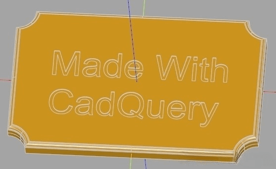
result = make_embossed_plate(text_lines, _cell_geometry)
32、带各种连接孔的面板

# The dimensions of the model. These can be modified rather than changing the
# object's code directly.
width = 400
height = 500
thickness = 2

# Create a plate with two polygons cut through it
result = cq.Workplane("front").box(width, height, thickness)

h_sep = 60
for idx in range(4):
    result = (
        result.workplane(offset=1, centerOption="CenterOfBoundBox")
        .center(157, 210 - idx * h_sep)
        .moveTo(-23.5, 0)
        .circle(1.6)
        .moveTo(23.5, 0)
        .circle(1.6)
        .moveTo(-17.038896, -5.7)
        .threePointArc((-19.44306, -4.70416), (-20.438896, -2.3))
        .lineTo(-21.25, 2.3)
        .threePointArc((-20.25416, 4.70416), (-17.85, 5.7))
        .lineTo(17.85, 5.7)
        .threePointArc((20.25416, 4.70416), (21.25, 2.3))
        .lineTo(20.438896, -2.3)
        .threePointArc((19.44306, -4.70416), (17.038896, -5.7))
        .close()
        .cutThruAll()
    )

for idx in range(4):
    result = (
        result.workplane(offset=1, centerOption="CenterOfBoundBox")
        .center(157, -30 - idx * h_sep)
        .moveTo(-16.65, 0)
        .circle(1.6)
        .moveTo(16.65, 0)
        .circle(1.6)
        .moveTo(-10.1889, -5.7)
        .threePointArc((-12.59306, -4.70416), (-13.5889, -2.3))
        .lineTo(-14.4, 2.3)
        .threePointArc((-13.40416, 4.70416), (-11, 5.7))
        .lineTo(11, 5.7)
        .threePointArc((13.40416, 4.70416), (14.4, 2.3))
        .lineTo(13.5889, -2.3)
        .threePointArc((12.59306, -4.70416), (10.1889, -5.7))
        .close()
        .cutThruAll()
    )

h_sep4DB9 = 30
for idx in range(8):
    result = (
        result.workplane(offset=1, centerOption="CenterOfBoundBox")
        .center(91, 225 - idx * h_sep4DB9)
        .moveTo(-12.5, 0)
        .circle(1.6)
        .moveTo(12.5, 0)
        .circle(1.6)
        .moveTo(-6.038896, -5.7)
        .threePointArc((-8.44306, -4.70416), (-9.438896, -2.3))
        .lineTo(-10.25, 2.3)
        .threePointArc((-9.25416, 4.70416), (-6.85, 5.7))
        .lineTo(6.85, 5.7)
        .threePointArc((9.25416, 4.70416), (10.25, 2.3))
        .lineTo(9.438896, -2.3)
        .threePointArc((8.44306, -4.70416), (6.038896, -5.7))
        .close()
        .cutThruAll()
    )

for idx in range(4):
    result = (
        result.workplane(offset=1, centerOption="CenterOfBoundBox")
        .center(25, 210 - idx * h_sep)
        .moveTo(-23.5, 0)
        .circle(1.6)
        .moveTo(23.5, 0)
        .circle(1.6)
        .moveTo(-17.038896, -5.7)
        .threePointArc((-19.44306, -4.70416), (-20.438896, -2.3))
        .lineTo(-21.25, 2.3)
        .threePointArc((-20.25416, 4.70416), (-17.85, 5.7))
        .lineTo(17.85, 5.7)
        .threePointArc((20.25416, 4.70416), (21.25, 2.3))
        .lineTo(20.438896, -2.3)
        .threePointArc((19.44306, -4.70416), (17.038896, -5.7))
        .close()
        .cutThruAll()
    )

for idx in range(4):
    result = (
        result.workplane(offset=1, centerOption="CenterOfBoundBox")
        .center(25, -30 - idx * h_sep)
        .moveTo(-16.65, 0)
        .circle(1.6)
        .moveTo(16.65, 0)
        .circle(1.6)
        .moveTo(-10.1889, -5.7)
        .threePointArc((-12.59306, -4.70416), (-13.5889, -2.3))
        .lineTo(-14.4, 2.3)
        .threePointArc((-13.40416, 4.70416), (-11, 5.7))
        .lineTo(11, 5.7)
        .threePointArc((13.40416, 4.70416), (14.4, 2.3))
        .lineTo(13.5889, -2.3)
        .threePointArc((12.59306, -4.70416), (10.1889, -5.7))
        .close()
        .cutThruAll()
    )

for idx in range(8):
    result = (
        result.workplane(offset=1, centerOption="CenterOfBoundBox")
        .center(-41, 225 - idx * h_sep4DB9)
        .moveTo(-12.5, 0)
        .circle(1.6)
        .moveTo(12.5, 0)
        .circle(1.6)
        .moveTo(-6.038896, -5.7)
        .threePointArc((-8.44306, -4.70416), (-9.438896, -2.3))
        .lineTo(-10.25, 2.3)
        .threePointArc((-9.25416, 4.70416), (-6.85, 5.7))
        .lineTo(6.85, 5.7)
        .threePointArc((9.25416, 4.70416), (10.25, 2.3))
        .lineTo(9.438896, -2.3)
        .threePointArc((8.44306, -4.70416), (6.038896, -5.7))
        .close()
        .cutThruAll()
    )

for idx in range(4):
    result = (
        result.workplane(offset=1, centerOption="CenterOfBoundBox")
        .center(-107, 210 - idx * h_sep)
        .moveTo(-23.5, 0)
        .circle(1.6)
        .moveTo(23.5, 0)
        .circle(1.6)
        .moveTo(-17.038896, -5.7)
        .threePointArc((-19.44306, -4.70416), (-20.438896, -2.3))
        .lineTo(-21.25, 2.3)
        .threePointArc((-20.25416, 4.70416), (-17.85, 5.7))
        .lineTo(17.85, 5.7)
        .threePointArc((20.25416, 4.70416), (21.25, 2.3))
        .lineTo(20.438896, -2.3)
        .threePointArc((19.44306, -4.70416), (17.038896, -5.7))
        .close()
        .cutThruAll()
    )

for idx in range(4):
    result = (
        result.workplane(offset=1, centerOption="CenterOfBoundBox")
        .center(-107, -30 - idx * h_sep)
        .circle(14)
        .rect(24.7487, 24.7487, forConstruction=True)
        .vertices()
        .hole(3.2)
        .cutThruAll()
    )

for idx in range(8):
    result = (
        result.workplane(offset=1, centerOption="CenterOfBoundBox")
        .center(-173, 225 - idx * h_sep4DB9)
        .moveTo(-12.5, 0)
        .circle(1.6)
        .moveTo(12.5, 0)
        .circle(1.6)
        .moveTo(-6.038896, -5.7)
        .threePointArc((-8.44306, -4.70416), (-9.438896, -2.3))
        .lineTo(-10.25, 2.3)
        .threePointArc((-9.25416, 4.70416), (-6.85, 5.7))
        .lineTo(6.85, 5.7)
        .threePointArc((9.25416, 4.70416), (10.25, 2.3))
        .lineTo(9.438896, -2.3)
        .threePointArc((8.44306, -4.70416), (6.038896, -5.7))
        .close()
        .cutThruAll()
    )

for idx in range(4):
    result = (
        result.workplane(offset=1, centerOption="CenterOfBoundBox")
        .center(-173, -30 - idx * h_sep)
        .moveTo(-2.9176, -5.3)
        .threePointArc((-6.05, 0), (-2.9176, 5.3))
        .lineTo(2.9176, 5.3)
        .threePointArc((6.05, 0), (2.9176, -5.3))
        .close()
        .cutThruAll()
    )
33、摆线齿轮
可以使用 parametricCurve 定义复杂的几何图形。 本实例生成螺旋摆线齿轮
import cadquery as cq
from math import sin, cos, pi, floor


# define the generating function
def hypocycloid(t, r1, r2):
    return (
        (r1 - r2) * cos(t) + r2 * cos(r1 / r2 * t - t),
        (r1 - r2) * sin(t) + r2 * sin(-(r1 / r2 * t - t)),
    )


def epicycloid(t, r1, r2):
    return (
        (r1 + r2) * cos(t) - r2 * cos(r1 / r2 * t + t),
        (r1 + r2) * sin(t) - r2 * sin(r1 / r2 * t + t),
    )


def gear(t, r1=4, r2=1):
    if (-1) ** (1 + floor(t / 2 / pi * (r1 / r2))) < 0:
        return epicycloid(t, r1, r2)
    else:
        return hypocycloid(t, r1, r2)


# create the gear profile and extrude it
result = (
    cq.Workplane("XY")
    .parametricCurve(lambda t: gear(t * 2 * pi, 6, 1))
    .twistExtrude(15, 90)
    .faces(">Z")
    .workplane()
    .circle(2)
    .cutThruAll()
)最后编辑:码峰 更新时间:2024-01-12 17:58